This is an overview and use of sensors for robotics systems.
The Arduino development board is based on Atmel processors. It is a cheap solution if you want to build your own robotic system. There are many good quality Chinese clones that you can buy cheap. You can also buy many other different ready-made modules to build your robotics system. There are ready-made kits for building robotic and automated systems.
There are also many forums and books where you can learn step-by-step how to program and use Arduino. The free software, low cost and easy setup makes the Arduino System a very popular choice around the world. Arduino can also be used to build measuring instruments for laboratories.
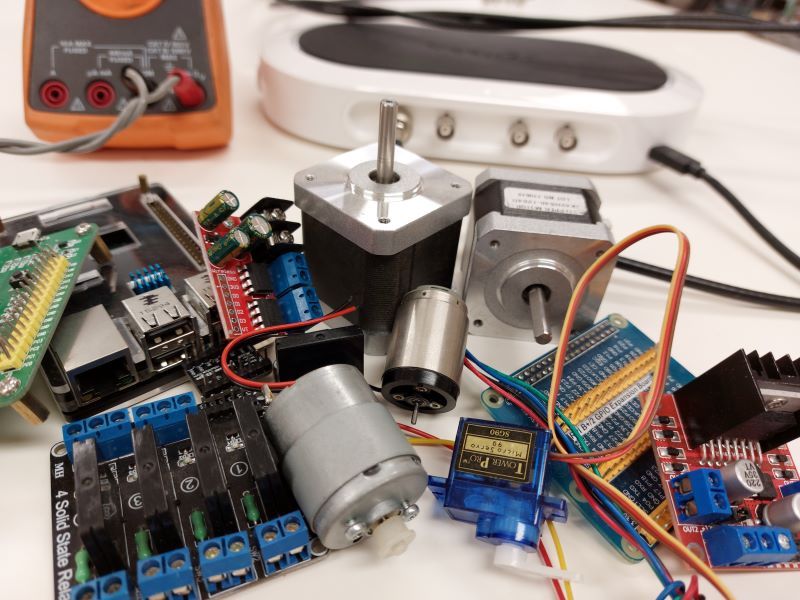
In this article, I would like to talk about stepper motors and their drivers. On Chinese websites you can buy numerous versions of stepper motors such as NEMA14 and NEMA17. These are cheap and very popular stepper motors in amateur robotics projects. There are two design assemblies. One is a stepper motor, and the other is a closed loop. The closed loop contains a PID controller circuit that implements feedback. This solution helps the stepper motor to move much more accurately and not skip steps, however, this solution significantly increases the cost of running the motor that is not very popular with robotics builders.
Stepper motors always comes in combination with a driver. The stepper motor driver controls the smoothness and accuracy of the motor, as well as the distance of its step and direction.
There are many kinds of stepper motor drivers available such as: DRV8825, A4988, L298N and TMC2208. These drivers are cheap and easy to connect to any control board. You can find many free cod versions in libraries on the internet that work with these drivers.
Each type of driver has its own special features, but there are still common features that will fit all stepper motor drivers.
The NEMA17 motor takes 200 steps per full circle of the axis, each step is 1.8 degrees. The motor has two phases. So, to connect it, the driver must have two channels each connected to one of the phases of the motor. All of the above drivers have common technical parameters.
1.8 degrees is the default step setting of the NEMA17 motor, but this is a very large step and not suitable for most purposes. Some drivers allow you to reduce this to 1/256th of a step. The drivers have input to power the motor and control pins to control it from the Arduino controller. Some drivers allow you to control two DC motors at the same time (not step motors).
For example, the L298N driver allows you to connect a DC motor to each channel and control them independently. This kind of driver is used to control the wheels of robots that move on wheels.
The ultrasonic distance sensor is the eyes of the robot. Using ultrasonic waves and their reflectivity, it is possible to calculate the distance to an object and thus avoid it or somehow interact with it. The ultrasonic sensor is a cheap solution, you can easily find code examples for Arduino on GitHub. You can use an ordinary camera, but in this case you need code for the computer vision, which will have a significant impact on the final price of the robot.
An infrared obstacle avoidance sensor is used when you want to detect the presence of an object but the distance to it is not important in contrast to the ultrasonic distance sensor.
The working principle is very simple. The infrared sensor reacts to the intensity of infrared radiation reflected in the monitored area. The infrared detector is used to drive the robot along a certain path, e.g., a white line. If the robot leaves the white line, the brightness of the reflection changes, indicating the robot is out of the white line and the corrective algorithm to return to the path will be activated. This sensor can also measure the speed of the object. If you put alternating stripes on the object, e.g., white and black stripes, it is easier to calculate the speed with the help of the intensity of reflection from the white strip. The TCS230 color sensor is also used in robotics. The color sensor is based on a similar principle whereby each color has its own frequency, and the sensor contains a set of photodiodes which are sensitive to the three main colors, namely, red, green and blue. Using the code we can switch the photodiodes responsible for a specific color and at the same time the output from the sensor will form a frequency responsible for a specific color applied to the sensor.
There are also universal sensors like APDS-9960 which combine three functions: movement, color and light. Using the ‘hand movements, the robot can be programmed so that each movement is responsible for a specific command. In setting the code, it is quite complicated, and I could write a whole article about it.
However, all these sensors are very easy to connect to the Arduino control board.
Conclusion
There are many sensors and types of motors on the market depending on your particular projects. Here are also open-source projects where you can get and use a variety of codes for free. There are also ready-made kits available for example the LEGO® Mindstorms® EV3.
Author: Peter Safir
Published: 9/1/2022